- New
LED dimmer to led strip soldering
Integration of an LED strip with a profile-mounted LED dimmer
 Delivery
1-3 dni (PL), 3-10 dni (non-PL)

Privacy Policy
 Return Policy
14 days
Integration of the ordered LED strip with a touch dimmer for LED profiles (index: 0029645).
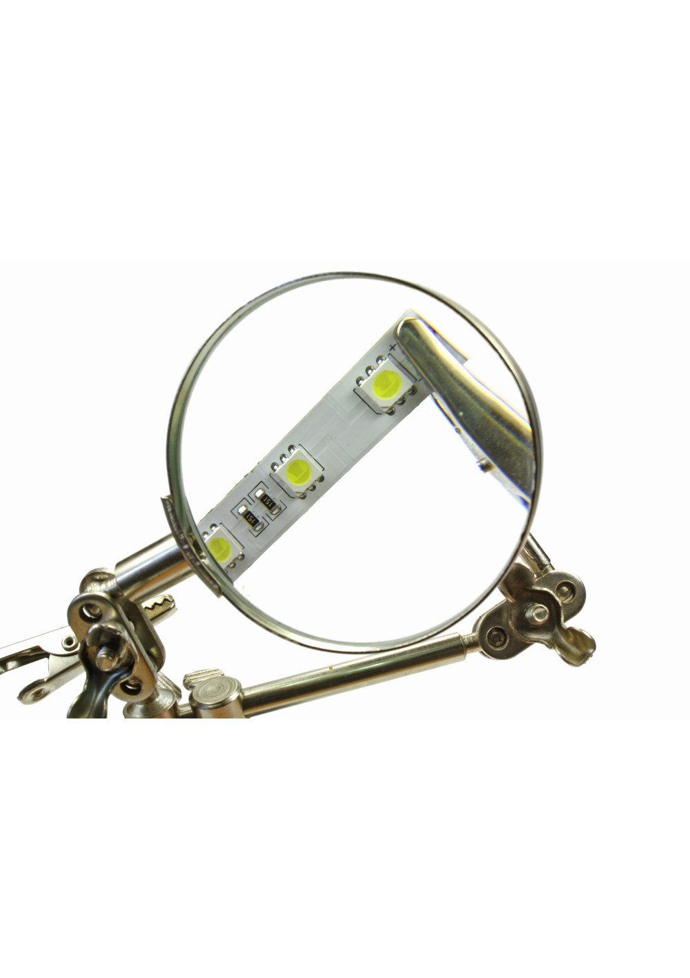
By ordering this service, you will receive the purchased LED strip integrated—professionally soldered and tested—with the ordered touch LED dimmer designed for in-profile installation (index: 0029645).
LED Strip Soldering — Best Practices for Reliable, Long-Life Installations
Professional soldering is crucial to the performance, safety, and lifespan of any LED strip installation. Below you’ll find recommended tools, a step-by-step technique, common pitfalls, and how mistakes can surface weeks or months later.
Essential Tools & Workplace Setup
-
Grounded, temperature-controlled soldering station (ESD-safe): reduces electrostatic discharge risk and prevents overheating copper pads and LEDs.
-
Fine or medium-mass tip (conical or chisel): enables quick heat transfer without “cooking” the PCB.
-
Electronics-grade flux (preferably no-clean) to improve wetting and shorten contact time.
-
Solder wire:
-
Leaded Sn60/Pb40 typically works around 300–330 °C.
-
Lead-free (e.g., SAC alloys) often needs 340–370 °C.
Final temperature depends on tip mass and dwell time—short heating is key.
-
-
ESD wrist strap and grounded mat, fine tweezers, side cutters, precision knife, magnifier, Kapton tape.
-
Heat-shrink tubing/strain relief, and neutral-cure silicone to re-seal IP65/IP67 strips after soldering.
Working With Delicate Components
-
LED chips and phosphor are heat-sensitive—excess heat can shift CCT, lower lumen output, and reduce life.
-
Copper pads can delaminate if overheated or pried with the tip.
-
Nearby SMD resistors/controllers may reflow or detach if you dwell too long.
Common Mistakes & How They Show Up Later
-
Overheating pads/tracks → pads lift, intermittent opens; segments flicker or go dark unpredictably.
-
Cold joints (dull, grainy, poorly wetted) → flicker, voltage drop, operation changes when the strip is touched or moved.
-
Solder bridges between pads → shorts, localized heating, premature driver/controller failure.
-
Wrong polarity → immediate no-light or permanent damage to the segment.
-
Undersized wires / long single-end feeds → voltage drop, brightness/CCT gradients along the strip.
-
No strain relief → cracked joints after weeks of thermal cycling or vibration.
-
No ESD precautions → latent semiconductor damage that surfaces as early-life failures.
-
Unrestored IP rating on sealed strips → corrosion, leakage, and yellowing/darkening over time.
Quality & Longevity Tips
-
Aim for short dwell time + correct temperature rather than “more heat for longer.”
-
Bench-test each joint on a correctly rated power supply before installing in profiles or coves.
-
Use multi-point power injection on long runs; treat aluminum profiles as heat sinks for better thermal performance.
-
Keep a clear wiring and polarity map for serviceability.
-
Separate control wiring (DALI/0–10 V/PWM) from power lines to minimize interference.
Bottom line: Proper LED strip soldering demands a grounded, temperature-controlled station, ESD control, and practiced SMD technique. Investing in correct methods today prevents callbacks tomorrow—delivering stable light quality, lower total cost of ownership, and long service life. If you prefer a ready-to-install solution, we provide professional soldering, cable harnessing, sealing, and validation tailored to premium LED systems.


